
How to Prepare Perfect Investment Casting Design Files for Production
August 13, 2026
Sending your design data to a manufacturing partner is the first critical step in bringing a metal component to life. Whether you are developing a prototype or moving straight to high-volume production, the quality of the information you provide directly impacts the speed and accuracy of your quote.
If you are providing CAD files to a foundry, incomplete or ambiguous data can create delays. By preparing your investment casting design files carefully, you enable the foundry to assess manufacturability immediately and identify the most efficient production methods for your project.
The Essentials of Investment Casting Design Files
The foundation of any modern manufacturing project is the 3D CAD model. This digital asset serves as the primary reference for creating the wax injection tool in investment casting or generating toolpaths for CNC machining. While native file formats from software like SolidWorks or Inventor are common, they can cause version compatibility issues if your manufacturer uses different software.
The industry standard is to provide a neutral 3D file format. A STEP (.stp or .step) file is universally accepted and retains the solid geometry required for tooling design. IGES (.igs) is another robust option. These formats ensure that the geometry you designed is exactly what the foundry receives.
When you submit your investment casting design files, ensure the model represents the final part geometry clearly. If you are expecting the foundry to add draft angles or shrinkage allowances, it is helpful to note this, but generally, you should design the part to its nominal dimensions and let the casting engineers apply the necessary process compensations.
Technical Drawing Standards and Critical Dimensions
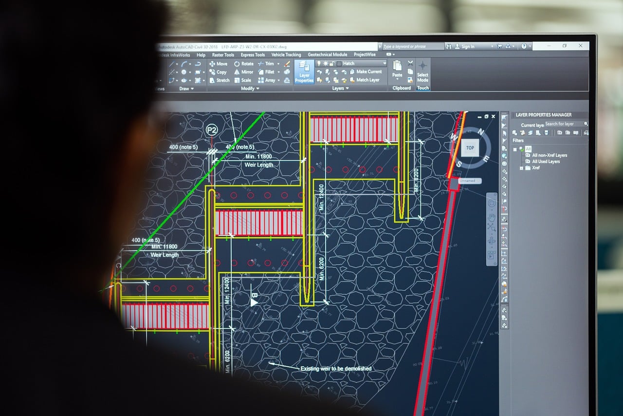
A 3D model tells the manufacturer the shape of the part, but it does not tell them the allowable variance. This is where the 2D engineering drawing becomes indispensable. You must include a PDF drawing alongside your 3D model to define critical tolerances, surface finishes, and threaded features.
Technical drawing standards help eliminate guesswork. Your 2D drawing should clearly identify:
- Dimensional Tolerances: Specify which dimensions are critical to function (CTF) and require tight control. Standard casting tolerances are looser than machining tolerances, so identifying critical areas helps the foundry decide where secondary machining is necessary.
- Threads and Fits: A 3D model rarely represents threads accurately. Call out thread sizes, types, and depths on the 2D drawing.
- Datum Structures: If you use Geometric Dimensioning and Tolerancing (GD&T), clearly mark your datum targets. This ensures the part is inspected exactly the way it will be used in the final assembly.
- Material Specifications: Clearly state the alloy grade (e.g., Stainless Steel 316, Carbon Steel WCB) and any required heat treatments or hardness values.
Optimizing 3D Models for Machining and Casting
Precision parts often require a combination of casting and secondary machining to meet final specifications. When you are optimizing 3D models for machining and casting, it helps to distinguish between the “as-cast” surfaces and the “machined” surfaces.
Ideally, your 3D model should represent the finished part. However, if you know certain faces will be machined, you can color-code those surfaces in the CAD model or explicitly mark them on the 2D drawing. This signals the foundry to add “machine stock” or extra material to those areas. This extra material ensures that when the machine tool cuts the surface, it cleans up perfectly to the required dimension without hitting low spots in the casting.
Furthermore, consider the internal geometry. Investment casting is famous for its ability to form complex internal channels and undercuts that are impossible to machine. Designing these features into the casting core can save significant time and money compared to drilling or boring them out later.
Casting CAD File Requirements Checklist
To ensure your project moves through the quoting and engineering phase without a hitch, run through this checklist before hitting send. Meeting these casting CAD file requirements allows the engineering team to validate your design faster.
- 3D Solid Model: STEP or IGES format.
- 2D Engineering Drawing: PDF format with all critical tolerances and datums defined.
- Material Grade: Specific alloy and any alternative acceptable grades.
- Quantity: Estimated Annual Usage (EAU) and batch sizes.
- Finishing Requirements: Heat treat, plating, painting, or polishing specs.
- Functionality Context: A brief note on what the part does or the assembly it fits into can help engineers suggest design improvements.
Moving From Design to Part
Clear communication is the key to a successful manufacturing partnership. By providing a complete package of 3D models and detailed 2D drawings, you give your manufacturing team the roadmap they need to deliver high-quality parts.
Texas Precision Metalcraft works closely with your engineering team to review these files, offering feedback to improve castability and reduce costs before tooling ever begins. If you are ready to turn your digital designs into precision metal components, our team is ready to help you navigate the process.